Reverse engineering "Vlak" (2)
Uncompressing data

In previous part I started reverse engineering a popular DOS game “Vlak” (train) made in 1993 by a Czech programmer Miroslav Němeček.
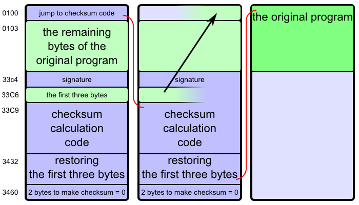
The first part of the program turned out to be a checksum validator, which was appended to the original game, and on start of the program it validated the checksum, displayed an error message if the check failed; and if the check succeeded, it restored the code of the original game in memory and started it.
Today we will continue analyzing the program…
A quick recapitulation of Intel 80286 architecture: There are 16-bit registers (integer variables implemented in processor hardware) called AX, BX, CX, DX, SI, DI, SP, CS, DS, ES, SS. The first four or them consist of pairs of 8-bit registers called AL, AH, BL, BH, CL, CH, DL, DH. There are also flags (boolean variables) called CF, DF, ZF, etc.
The relation between the 8-bit and respective 16-bit registers is AX = 100 × AH + AL, etc. A place in memory is addressed by a combination of “segment” (CS, DS, ES, SS) and “offset” (any other register, or a numeric constant) like this: 10 × segment + offset.
All numbers written in this article are hexadecimal unless specified otherwise, so by “10” I actually mean sixteen, and by “100” I mean two hundred and fifty six.
At the beginning, the registers CS, DS, ES, SS are all set up to point at a free block of memory where the program was loaded, so that the program starts at CS:0100.
0100  cmp   sp, adc8
0104  jb    0123
0106  mov   di, abc6
0109  mov   cx, 65
010C  mov   si, 01f4
010F  std
0110  rep movsw
0112  jmp   aafe
First, the program checks whether the stack is sufficiently large.1 If not, it jumps to CS:0123, where it prints an error message “Memory error” (in Czech) and terminates.
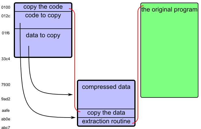
The part “std; rep movsw” copies a part of memory, one word (a pair of bytes) at a time. Instruction “std” sets the direction flag DF to true; we will copy data in a backward direction. The previous lines initialize the values. CX is set to 65, which means we will copy 65 words, that is ca bytes.
SI = 01f4 is the starting address, DI = abc6 is the destination address, but we copy the words backwards: first the bytes at 01f4 and 01f5 to abc6 and abc7, then the bytes at 01f2 and 01f3 to abc4 and abc5, and so on, always decreasing SI and DI by two. This will copy the bytes from 012c to 01f5 (inclusive) to aafe to abc7 (inclusive).
Then the program continues at CS:aafe — the copied code.
AAFE  mov   si, 33c2
AB01  mov   cx, 18e7
AB04  rep movsw
AB06  cld
AB07  mov   si, 7930
AB0A  mov   di, 0100
AB0D  push  di
Again, a memory block is copied. This time it is 18e7 words, i.e. 31ce bytes2 from memory addresses 01f6 to 33c3 (inclusive) to 7930 to aafd (inclusive). The contents of the memory were almost completely rearranged.
Then the program sets SI to 7930 (the beginning of the copied data), and pushes 0100 (the beginning of the program) to stack.
Let me reveal the secret:3 The following code is going to extract compressed data in memory. The previous instructions were moving the compressed data and the extraction routine out of the way. Now the actual fun starts.
The author of the game implemented a kind of LZ compression — a family of algorithms also used e.g. in ZIP files. The idea is that if you have data that is not random noise, sometimes small parts of it repeat. You can save some space if instead of repeating those parts verbatim you just say “and here is another copy of the bytes from X to Y”, assuming that you can say it in a way that takes fewer bits than the original sequence. But most of those sequences will be very short (maybe only 2 or 3 bytes), so every bit matters.
The program will read a stream of compressed data and commands from DS:SI and write a stream of uncompressed data to ES:SI, until it encounters a “stop” command.
How will the program read data and instructions from the same input stream, if the data are bytes, but the commands are bits? (Also, DS:SI points to a specific byte the in memory, not a specific bit.) The answer is that the program will always read 16 bits at a time, store them in AX, and when it runs out of the stored bits, it will read 16 more.
There is a sequence of code that repeats a lot in the following part of the program:
....  shr   ax, 1
....  jnz   nnnn
....  lodsw
....  rcr   ax, 1
nnnn  rcl   .., 1
This means: “push another bit to the register mentioned in the last instruction (CX or BH); if you have run out of stored bits, read 16 more bits from DS:SI to AX”.
To see how this works, we need to understand the bit-rotating instructions “shr”, “rcr”, “rcl”.
We can imagine the 16-bit registers and 8-bit registers as containing binary numbers consisting of given number of ones and zeroes; that is 16 digits for AX or CX, and 8 digits for BH. We imagine them written the usual way, with the higher-order digits to the left, and the lower-order digits to the right.
Instruction “shr register, count” shifts the binary digits in given register to the right by the specified number of positions. For example, shifting 1111 0000 to the right by one position gives us 0111 1000; shifting 0000 1111 to the right by one gives us 0000 0111. When shifting by one, the original rightmost (lowest-order) digit gets removed from the register, and stored in the flag CF. The leftmost (highest-order) digit in the result is set to zero.
Also, as a side effect of the instruction, the value of ZF (zero flag) is set to true if the final value in the register is equal to zero, that is if the binary number consists only of zeroes, that is 0000 0000 for a 8-bitr register; otherwise the value of ZF is set to false.
Instruction “rcr register, count” does almost the same thing, except the leftmost (highest-order) digit in the result is set to the original value of CF. That is, the bits of the register and the CF are rotated to the right.
Another way to put the difference is that if we ran an instruction “shr AX, 1” sixteen times, at the end the register would only contain zeroes, as its original bytes were one by one pushed out at the right end. But if we ran an instruction “rcr AX, 1” seventeen times, at the end the original value of the register would be restored, as its original bytes one by one moved to the right end, then to CF, and then back from the left end.
Instruction “rcl register, count” is the same as “rcr”, but to the left. When rotating by one, the leftmost bit goes to CF, and the original value of CF goes to the rightmost (lowest-order) bit.
(If you understand binary numbers, you see that rotating by one digit to the right is like dividing by two, and rotating by one digit to the left is like multiplying by two.)
In this part of program, the register AX contains the stored bits, preceded by a single 1 digit and the remaining number of 0 digits. For example AX = 0010 1100 means that the stored bits are “01100”. AX = 0000 0001 means that no more bits are stored.
So, instruction “shr ax, 1” moves the rightmost bit from AX to CF, shifting the remaining bits by one. If AX originally contained 0000 0001 (empty bit store), now it contains 0000 0000, CF is true (because 1 was shifted out of AX), and ZF is also true (because AX is zero).
If ZF is false — that is, if some bits still remained in AX — the following part is skipped.
Instruction “lodws” reads new 16 bits to AX. Instruction “rcr AX, 1” moves the rightmost bit from AX to CF, and moves the original CF (which was true after the previous instruction) to the leftmost bit of AX. Now again the invariant “AX contains the stored bits, preceded by a single 1 digit” is fulfilled, and the CF contains the next bit.
That means, either way, when the following instruction “rcl register, 1” runs, CF contains the next bit from the input stream.
Okay, here starts the decompressing algorithm:
AB0E  stc
AB0F  jmp   ab16

AB11  movsb

      ; main loop starts here
AB12  shr   ax, 1  ; read the first bit (fetch the next 16 bits if necessary)
AB14  jnz   ab19
AB16  lodsw
AB17  rcr   ax, 1

AB19  jnc   ab11  ; command "0": copy one byte from input to output

AB1B  xor   bx, bx  ; BL := 0
AB1D  xor   cx, cx  ; CX := 0
The main loop starts at address AB12. The program reads the next bit of command, and decides accordingly.
The program enters the loop by jumping in the middle of the “read next input bit” block, skipping the “shr, jnz” instructions that check whether AX contain some bits (because AX is not initialized yet), reading the next 16 bits into AX.
If the command bit is “0”, it means “copy one byte from input stream to output stream”. The program jumps to AB11, copies the bit, and continues the loop.
If the command bit is “1”, it means “duplicate C bytes that were already written to output stream, starting B bytes behind the end of the output stream”, and now we are going to calculate the values of C and B. We start by initializing CX and BX to zero.
AB1F  shr   ax, 1  ; read the next bit (fetch the next 16 bits if necessary)
AB21  jnz   ab26
AB23  lodsw
AB24  rcr   ax, 1
AB26  rcl   cx, 1  ; write the next bit to CX

      ; loop for calculating CX starts here
AB28  inc   cx  ; CX := CX + 2
AB29  inc   cx

AB2A  shr   ax, 1  ; read the next bit (fetch the next 16 bits if necessary)
AB2C  jnz   ab31
AB2E  lodsw
AB2F  rcr   ax, 1

AB31  jnc   ab3a  ; if the bit was 0, stop calculating CX and go to the next part

AB33  cmp   cl, 16
AB36  jb    ab28  ; if CL >= 16, add 2, then stop calculating CX
AB38  inc   cx
AB39  inc   cx
The value CX is calculated by a loop. First, it is assigned the next bit from input stream, that is either 0 or 1.
In the loop, CX is increased by 2. If the next bit from input stream is “0”, we end this part. If it was “1”, and CX is still less that 16 hexadecimal (22 binary), continue the loop. If it was “1” and CX is already 16 or more, increase CX by 2 and end this part.
That means, the values of CX at the end of this part depend on the input bits like this: “00” = 2, “10” = 3, “010” = 4, “110” = 5, “0110” = 6, “1110” = 7, …, “0111 1111 1110” = 16, “1111 1111 1110” = 17, “0111 1111 1111” = 18, “1111 1111 1111” = 19 (hexadecimal).
AB3A  cmp   cl, 7
AB3D  jb    ab4d
AB3F  ja    ab4c
AB41  mov   cl, [si]  ; if CL = 7
AB43  cmp   cl, ff
AB46  je    abba
AB48  inc   si
AB49  add   cx, 1a
AB4C  dec   cx        ; if CL > 7
If CX was between 2 and 6, it remains as it was calculated in the previous step.
If CX was between 8 and 19 (hexadecimal), subtract one, so now it is between 7 and 18.
If CX was exactly 7 (if the input bits were “1110”), it is a special case. Read another byte from the input stream. If that byte is ff, the decompression algorithm ends. If it was something else, then CX becomes 19 plus that new byte, so now it is between 19 and 117.
This is the final value of CX, how many bytes are we going to copy to output stream. Now we are going to determine where to copy them from.
The value of BX consists of two bytes, BH and BL. First we determine BH:
AB4D  cmp   cx, 2  ; if CX = 2, BH = 0, skip this part
AB50  je    abaa

AB52  shr   ax, 1  ; read the next bit (fetch the next 16 bits if necessary)
AB54  jne   ab59
AB56  lodsw
AB57  rcr   ax, 1

AB59  jc    abaa   ; bit "1" means BH = 0

AB5B  shr   ax, 1  ; read the next bit (fetch the next 16 bits if necessary)
AB5D  jne   ab62
AB5F  lodsw
AB60  rcr   ax, 1

AB62  rcl   bh, 1  ; push the next bit into BH

AB64  shr   ax, 1  ; read the next bit (fetch the next 16 bits if necessary)
AB66  jne   ab6b
AB68  lodsw
AB69  rcr   ax, 1

AB6B  rcl   bh, 1  ; push the next bit into BH

AB6D  shr   ax, 1  ; read the next bit (fetch the next 16 bits if necessary)
AB6F  jne   ab74
AB71  lodsw
AB72  rcr   ax, 1

AB74  rcl   bh, 1  ; push the next bit into BH
      ; BH is between 00 and 07

AB76  cmp   bh, 1  ; if BH is 00 or 01
AB79  jbe   aba8   ; make it 01 or 02 and go to the next part
      ; otherwise BH is between 02 and 07

AB7B  shr   ax, 1  ; read the next bit (fetch the next 16 bits if necessary)
AB7D  jne   ab82
AB7F  lodsw
AB80  rcr   ax, 1

AB82  rcl   bh, 1  ; push the next bit into BH
AB84  dec      bh
      ; BH is between 03 and 0E

AB86  cmp   bh, 6  ; if BH is between 03 and 06
AB89  jbe   abaa   ; go to the next part
      ; otherwise BH is between 07 and 0E

AB8B  shr   ax, 1  ; read the next bit (fetch the next 16 bits if necessary)
AB8D  jne   ab92
AB8F  lodsw
AB90  rcr   ax, 1

AB92  rcl   bh, 1  ; push the next bit into BH
AB94  sub   bh, 7
      ; BH is between 07 and 16

AB97  cmp   bh, 0d  ; if BH is between 07 and 0D
AB9A  jbe   abaa   ; go to the next part
      ; otherwise BH is between 0E and 16

AB9C  shr   ax, 1  ; read the next bit (fetch the next 16 bits if necessary)
AB9E  jne   aba3
ABA0  lodsw
ABA1  rcr   ax, 1

ABA3  rcl   bh, 1  ; push the next bit into BH
ABA5  sub   bh, 0f
      ; BH is between 0D and 1E

ABA8  inc   bh
Depending on the 1 or 4 or 7 bits read from input, the value of BH is between 00 and 1d.
BL is simply the next byte from the input stream:
ABAA  mov   bl, [si]
ABAC  inc   si
Now we have in BX a value betweeen 0000 and 1dff, and we will copy the bytes.
ABAD  mov   dx, si  ; store the input stream address in DX
ABAF  mov   si, di  ; copy bytes from address at DI-BX (BX bytes back in the output stream)
ABB1  sub   si, bx
ABB3  rep movsb
ABB5  mov   si, dx   ; restore the input stream address
ABB7  jmp   ab12     ; continue the main loop
Instruction “rep movsb” makes CX repetitions of “movsb” (move a byte from DS:SI to ES:DI, and depending on DF increase or decrease the values of SI and DI to point to the next byte).
Yep, that’s it. This is the code for LZ decompression in binary code.
You can find a Python version of the same code here. It is quite ugly, because it is essentially the same binary code rewritten using Python syntax.
The rest of the code is:
ABBA  xor   ax, ax
ABBC  xor   bx, bx
ABBE  xor   cx, cx
ABC0  xor   dx, dx
ABC2  xor   si, si
ABC4  xor   di, di
ABC6  ret
This sets the registers to zero, and starts the original program (now unpacked in the memory). Remember the “push di, 0100; push di” instructions before the decompression routine? They pushed the address 0100 (the beginning of the program) to stack. Instruction “ret” now reads the address from the stack, and jumps there.
As a reminded, I originally wanted to reverse engineer a game, but first I reverse engineered a checksum validator, and now an in-memory data decompressor. Even worse, I originally chose a very short program on purpose, but after decompression it is about three times as long.
Perhaps the third time is the charm?
Later we will see that the program uses memory up to CS:abc7. Comparing the stack pointer to adc8 means making sure that there will be at least 200 bytes for the stack.
That is almost the entire program! After validating checksum, 12996 (decimal) bytes of the original program remained, and now we are going to copy 12750 (decimal) of them.
I had to figure it out for myself by reading the code, and although I’d like to show you the original experience, it would make this article too long. Reading an instruction by instruction, having no idea what the big picture is, only to have it click together at some moment, and now the code suddenly makes sense when you look at it again, is an interesting experience, but it probably cannot be transmitted by written words.